2020-07-07 17:26:19 Editor:凯福
The working principle of the stepper motor is actually the principle of the action of the electromagnet.
It is an open loop control element stepper motor that converts the electrical pulse signal into angular displacement or linear displacement. By controlling the sequence, frequency and number of electrical pulses applied to the motor coil, the steering, speed and rotation Angle of the stepper motor can be controlled. With the linear motion actuator or gear box device, more complex and precise linear motion control requirements can be realized.

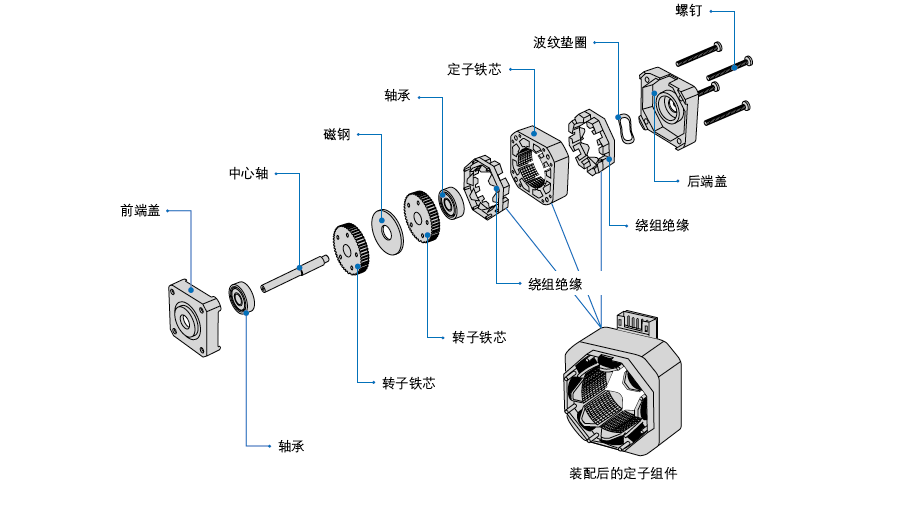
Stepper motor is generally composed of front and rear end covers, bearings, central shaft, rotor core, stator core, stator components, corrugated washers, screws and other parts, stepper motor is also called stepper, it uses the principle of electromagnetism, the electrical energy into mechanical energy, is wound in the motor stator tooth slot on the coil driven. Normally, a wire wound in a loop is called a solenoid, and in a motor, the wire wound around the stator tooth slot is called a winding, coil, or phase. The direction of the motor is related to the phase sequence of the power, and the direction of the motor will change if the phase sequence of the power is changed. Each input pulse signal, the rotor rotates an Angle or further forward, the output angular displacement or linear displacement is proportional to the number of input pulses, and the speed is proportional to the pulse frequency. The speed of the motor is related to the frequency of phase-sequence switching, and the faster the switching, the faster the motor rotates.
Stepper motor winding form
Stepper motors have two winding forms: bipolar and unipolar. Bipolar motor The type of bidirectional current flowing through one coil. There is only one winding coil on each phase. When the motor rotates continuously, the current changes to the same coil in turn, and the drive circuit design requires eight electronic switches for sequential switching. Unipolar motor A type in which only unidirectional current flows through one coil. There are two winding coils of opposite polarity on each phase, and the two winding coils on the same phase are energized alternately when the motor is continuously rotating. The drive circuit design requires only four electronic switches. The control circuit is simple, but it cannot obtain the high torque of the bipolar type. In bipolar drive mode, because the winding coil of each phase is 100% excited, the output torque of the motor in bipolar drive mode is about 40% higher than that in unipolar drive mode. |
Diagram of winding of 2-phase (bipolar) stepper motor |
Diagram of winding of 2-phase (unipolar) stepper motor |
Step Angle
The stepper motor rotates at a fixed step Angle, like the second hand in a clock. This Angle is called the basic step Angle. Step Angle θ=360 degrees/(number of rotor teeth × number of running beats). The step Angle of the motor represents the Angle of rotation of the motor for each pulse signal sent by the control system. In other words, the Angle of rotation of the rotor for each input pulse electrical signal is called the distance Angle and is represented by θ. Take the conventional two - and four-phase motors with 50-tooth rotor teeth as an example. The step Angle of four-beat running time is θ=360 degrees/(50×4) =1.8 degrees (commonly known as full step), and the step Angle of eight-beat running time is θ=360 degrees/(50×8) =0.9 degrees (commonly known as half step). Conventional motor step Angle is 1.8°, 1.2°, 0.9°, 0.72°, less used 1.5°, 3.6°, 3.75° through the reducer to achieve 0.018° and other small angles, specific matters can contact the company personnel for matching. |
|
Extended reading:
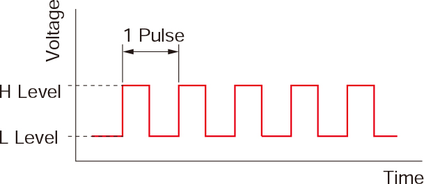
Pulse signal A pulse signal is an electrical signal whose voltage repeatedly changes between ON and OFF. Each ON/OFF cycle is recorded as a pulse. A single pulse signal instructs the motor output shaft to rotate one step. The signal level for the corresponding voltage ON and OFF is called "H" and "L" respectively. |  |
The rotational distance is proportional to the number of pulses The turning distance of the stepper motor is proportional to the number of pulse signals applied to the driver (pulse number). The relationship between stepper motor rotation (motor output shaft rotation Angle) and pulse number is as follows:
|
|
The speed is proportional to the pulse frequency The speed of the stepper motor is proportional to the frequency of the pulse signal applied to the driver. The relationship between the motor speed [r/min] and the pulse frequency [Hz] is as follows (step mode) :
|
|
More stepper motor working principle and solution, welcome to understand the consultation. We have also sorted out the selection and calculation formula of the stepper motor, and the details can also be clicked on the link blue font to enter the corresponding webpage.